15

Expanding on this question. I am looking at a few different ways to hook up a HD44780 to the GPIO pins and the various tradeoffs.

Here's my "world clock" running off a RPi using I²C RPi running 3 HD44780 displays via I²C

So far I've just got one working using 6 GPIO pins similar to the tutorial at Adafruit and an I²C version using a MCP23017

Other ideas I would like to get working are:

The 6 GPIO pin version is simple, but uses 6 valuable GPIO pins
The CD4094 version is very cheap and only needs 2 GPIO pins
The I²C version is only slightly more expensive, but can run up to 6 displays with a single MCP23017 and share the I²C with other devices

Can anyone think of other options to try?

John La Rooy
  • 11,947
  • 9
  • 47
  • 75
  • Have a look at this: http://www.schnatterente.net/technik/raspberry-pi-rss-reader-hd44780-display It's a real cool RSS Reader for Raspberry Pi + HD44780 Display! :) –  Oct 12 '12 at 16:30

2 Answers2

5

6 GPIO pins

Here is the code I am currently using. So far just GPIO is working. Look at the test_gpio function to see/change which GPIO pins are connected to which pins on the LCD module.

import time
import RPi.GPIO as GPIO

class LCD_GPIO(object): # Timing constants E_PULSE = 0.00005 E_DELAY = 0.00005 def init(self, RS, E, D4, D5, D6, D7): self.RS = RS self.E = E self.D4 = D4 self.D5 = D5 self.D6 = D6 self.D7 = D7

    GPIO.setmode(GPIO.BCM)        # Use BCM GPIO numbers
    GPIO.setup(self.E, GPIO.OUT)  # E
    GPIO.setup(self.RS, GPIO.OUT) # RS
    GPIO.setup(self.D4, GPIO.OUT) # DB4
    GPIO.setup(self.D5, GPIO.OUT) # DB5
    GPIO.setup(self.D6, GPIO.OUT) # DB6
    GPIO.setup(self.D7, GPIO.OUT) # DB7

def lcd_byte(self, data, mode):
    GPIO.output(self.RS, mode)

    for bits in (data>>4, data):
        GPIO.output(self.D4, bits&0x01)
        GPIO.output(self.D5, bits&0x02)
        GPIO.output(self.D6, bits&0x04)
        GPIO.output(self.D7, bits&0x08)

        # Toggle E
        time.sleep(self.E_DELAY)
        GPIO.output(self.E, True)
        time.sleep(self.E_PULSE)
        GPIO.output(self.E, False)
        time.sleep(self.E_DELAY)


class LCD_23017(object): pass

class LCD_4094(object): pass

class HD47780(object): LCD_CHR = True LCD_CMD = False # Base addresses for lines on a 20x4 display LCD_BASE = 0x80, 0xC0, 0x94, 0xD4

def __init__(self, driver, rows=2, width=16):
    self.rows = rows
    self.width = width
    self.driver = driver
    self.lcd_init()

def lcd_init(self):
    # Initialise display
    lcd_byte = self.driver.lcd_byte
    for i in 0x33, 0x32, 0x28, 0x0C, 0x06, 0x01:
        lcd_byte(i, self.LCD_CMD)


def lcd_string(self, message):
    # Send string to display
    lcd_byte = self.driver.lcd_byte
    lcd_byte(self.LCD_BASE[0], self.LCD_CMD)
    for i in bytearray(message.ljust(self.width)):
        lcd_byte(i, self.LCD_CHR)

def test_gpio(): driver = LCD_GPIO(RS=7, E=8, D4=25, D5=24, D6=23, D7=18) lcd = HD47780(driver=driver, rows=4, width=20) lcd.lcd_string("Welcome gnibbler")

def main(): test_gpio()

if name == "main": main()

John La Rooy
  • 11,947
  • 9
  • 47
  • 75
5

I²C

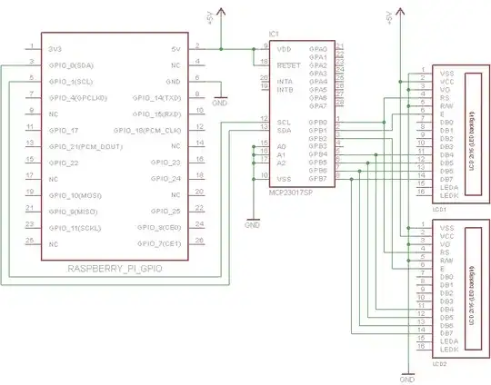
Hooking it up is fairly straightforward. The contrast pin(VO) of the particular displays I am using needs to be connected to ground. Usually you would connect it to a potentiometer to set the voltage between VSS and VCC

My displays don't have a backlight, so I haven't connected those to reduce clutter on the schematic. If yours has a backlight you should of course connect it in the usual way

You can connect up to 3 displays in parallel to each port of the MCP23017. The only difference is the enable pin from each display needs to connect to a separate pin (GPB1-GPB3)

Raspberry Pi driving HD44780 via MCP23017

#!/usr/bin/env python
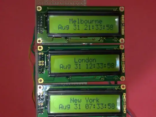
"""World Clock Demo
   It should be fairly obvious how to change this code to work for other timezones"""
import time

class LCD_23017(object): # Timing constants E_PULSE = 0.00005 E_DELAY = 0.00005 def init(self, bus, addr, port, rs, en): self.bus = bus self.addr = addr self.rs = rs self.en = en

    self.DIRECTION = 0x00 if port == 'A' else 0x01
    self.DATA = 0x12 if port == 'A' else 0x13

    self.bus.write_byte_data(addr, self.DIRECTION, 0x00)

def lcd_byte(self, data, rs):
    rs <<= self.rs
    en = 1 << self.en
    for nybble in (data&0xf0, data<<4):
        self.bus.write_byte_data(self.addr, self.DATA, nybble | rs)
        time.sleep(self.E_DELAY)
        self.bus.write_byte_data(self.addr, self.DATA, nybble | rs | en)
        time.sleep(self.E_PULSE)
        self.bus.write_byte_data(self.addr, self.DATA, nybble | rs)


class HD47780(object): LCD_CHR = True LCD_CMD = False # Base addresses for lines on a 20x4 display LCD_BASE = 0x80, 0xC0, 0x94, 0xD4

def __init__(self, driver, rows=2, width=16):
    self.rows = rows
    self.width = width
    self.driver = driver
    self.lcd_init()

def lcd_init(self):
    # Initialise display
    lcd_byte = self.driver.lcd_byte
    for i in 0x33, 0x32, 0x28, 0x0C, 0x06, 0x01:
        lcd_byte(i, self.LCD_CMD)

def lcd_string(self, message, line=0):
    # Send string to display
    lcd_byte = self.driver.lcd_byte
    lcd_byte(self.LCD_BASE[line], self.LCD_CMD)
    for i in bytearray(message.ljust(self.width)):
        lcd_byte(i, self.LCD_CHR)


def test_i2c(): from datetime import datetime import pytz import smbus

## For Rev1.0 Raspberry Pi
driver1 = LCD_23017(bus=smbus.SMBus(0), addr=0x27, port='B', rs=0, en=1)
driver2 = LCD_23017(bus=smbus.SMBus(0), addr=0x27, port='B', rs=0, en=2)
driver3 = LCD_23017(bus=smbus.SMBus(0), addr=0x27, port='B', rs=0, en=3)

## For Rev2.0 Raspberry Pi
#driver1 = LCD_23017(bus=smbus.SMBus(1), addr=0x27, port='B', rs=0, en=1)
#driver2 = LCD_23017(bus=smbus.SMBus(1), addr=0x27, port='B', rs=0, en=2)
#driver3 = LCD_23017(bus=smbus.SMBus(1), addr=0x27, port='B', rs=0, en=3)


lcd1 = HD47780(driver=driver1, rows=2, width=16)
lcd2 = HD47780(driver=driver2, rows=2, width=16)
lcd3 = HD47780(driver=driver3, rows=2, width=16)
lcd1.lcd_string("    New York")
lcd2.lcd_string("     London")
lcd3.lcd_string("    Melbourne")
new_york_tz = pytz.timezone("America/New_York")
london_tz = pytz.timezone("Europe/London")
melbourne_tz = pytz.timezone("Australia/Melbourne")
while True:
    time.sleep(1-time.time()%1)  # Wait until the next second
    lcd1.lcd_string(datetime.now(new_york_tz).ctime()[3:], line=1)
    lcd2.lcd_string(datetime.now(london_tz).ctime()[3:], line=1)
    lcd3.lcd_string(datetime.now(melbourne_tz).ctime()[3:], line=1)

def main(): test_i2c()

if name == "main": main()

John La Rooy
  • 11,947
  • 9
  • 47
  • 75
  • Thanks. It works!. This great post helps me a lot. Only a comment for newbies (like me). If you use a Raspberry Rev.2, use bus=smbus.SMBus(1) instead of bus=smbus.SMBus(0) in the code. The adress can be determined by running this command: "sudo i2cdetect -y 1" (use 0 instead 1 for Raspberry Rev.1). In my case was 0x20 instead of 0x27. Thanks a lot. –  Sep 10 '13 at 18:19