The pictures and text on the eBay page you have linked imply that the relay you have bought should work for your application. I say that because they do claim (at least) that the product is set up for use with Raspberry Pi and Arduino; the pictures show what appears to be peripheral circuitry that might be level shifters to take the 3.3v output at your GPIO pins, and drive the relay. If that's the case, you should be able to control your mag lock directly from an appropriate GPIO pin. If not, please refer to this answer for some ideas on how to interface a relay to the RPi GPIO.
You are correct that the RPi won't supply the 12 v you need for the mag lock. You'll need to supply 12 VDC... it won't come directly from "the wall" as "wall outlets" provide 220v/50 Hz AC (or 120v/60 Hz in the US). However, a standard "wall wart" rated at 12 vdc that plugs into the "the wall" will supply the power you need (probably what you meant, just making sure). The current required from your "wall wart" will likely not be more than 1-2 amps, but you should be able to get that specification from your mag lock vendor.
The hookup between the RPi, your relay board and mag lock are shown in the diagram below.
Since the specs on the relay are so "iffy", you should proceed with caution. Ideally, you would apply power to the relay board (disconnected from your RPi), then measure the voltage at the relay board's input pin(s). If they're 0 volts, then apply 3.3V from an external source to the input to test function of the relay's contacts. You may also want to control an LED before you connect your mag lock. This advice is offered to: a) protect your RPi, and b) avoid wasting time and effort with a useless "relay board".
One other point: The relay coils in your relay board & the MagLock device will have an "inductive kick" when current flow through them is stopped. It is important to the reliability of your RPi and your circuit that that this "inductive kick" be suppressed at its source. Failure to suppress "inductive kick" will lead to potential malfunctions & reduced component life.
The "inductive kick" suppression may have been incorporated in the design of the MagLock device, and the relay board, but you should check the specs/schematics to verify this. If not, you should add that yourself. This can typically be done with 1 or 2 components. If after reviewing the documentation you're still unsure, re-post here, and we'll come up with a simple "protective circuit" to keep your RPi and your relay board out of harm's way.
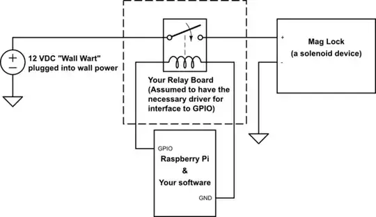
simulate this circuit – Schematic created using CircuitLab