I'm running a Pi B+ rev 1.2 and recently acquired 2 I2C modules:
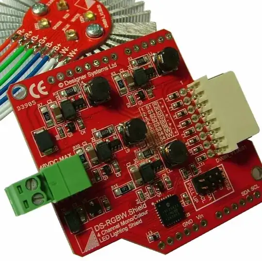
DS-RGBW.S LED lighting
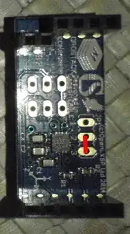
Microstack accelerometer:

When connecting the LED module, address 70 appears to be occupied as planned. I modify the script to use SMBus(1) instead of SMBus(0). Script runs, but no response. When terminating the script, python claims to have been at line 96, time.sleep(000.1). None of the lights have been on. The 48VDC terminal is not used, but I'm not sure it's even supposed to be used. Attached to pin 3/4/5/6 as shown on the diagram given by the supplier.
So, ok. It might be from a bad batch, so I hooked up the accelerometer. I don't have the baseboard, but it fits just fine without (on pin 1/3/5/7/9/11)(leaving the 4+2 pins not connected). But now I i2cdetect -y 1 shows an empty address table.
Yes, I did reboot after installing all required dependencies and yes all required configurations have been modified. I'm running the latest software on the latest Raspbian. How should I debug my I2C trouble? Anyone experience with problems like these?
If any pertinent information is missing, please comment.
Update:
Script called is from this zip file as stated in the product manual. /RGBW.S_Disk/R-PI/RGBW.py
# Designer Systems DS-RGBW LED Lighting Shield Raspberry-PI Demonstrator

# Requires Raspberry-PI A or B board

# DS-RGBW.S [A0 & A1 jumpers ON] connected to I2C interface (GPIO pin 3 SDA, pin 5 SCL)

# RGBW.py   Date: 13/7/13   Version: 1.00

# Run from LX terminal window using 'sudo python RGBW.py

# Fades WHITE up/down, outputs a number of RGB colours and then cycles through colour wheel

# Note: May require I2C setup procedure on R-PI

# Use CTRL+C to exit


# import modules needed for this application
import smbus
import time

# NOTE: THE ZERO IN THE COMMAND BELOW MAY NEED CHANGING TO A '1' DEPENDING ON THE RASPBERRY PI USED
bus = smbus.SMBus(1)

# Define DS-RGBW.S I2C address
address = 0x70

# Routine to write to I2c register from DS-RGBW.S
def writeRegister (register, value):
    bus.write_byte_data(address, register, value)

# Routine to write to I2c,define registers
def writeRGBWregisters (red, green, blue):
    bus.write_byte_data(address,3,red)
    bus.write_byte_data(address,4,green)
    bus.write_byte_data(address,5,blue)

# Routine to write to i2c, define registers
def writeHSBregister (hue,saturation,brightness):
    bus.write_byte_data(address,6,hue)
    bus.write_byte_data(address,7,saturation)
    bus.write_byte_data(address,8,brightness)

# Main program
while True:

# All off
    bus.write_byte_data(address,2,0)
    bus.write_byte_data(address,3,0)
    bus.write_byte_data(address,4,0)
    bus.write_byte_data(address,5,0)

# Fade white LED from 0 to 99%
for data in range(0,99):
    writeRegister(2,data)
            time.sleep(0.01)

# Fade white LED from 99 to -1
for data in range(99,-1,-1):
    writeRegister(2,data)
            time.sleep(0.01)

# Sleep 2 second
    time.sleep(2)

# Send RGBW colour (Pink)
    writeRGBWregisters(255,88,67)

# Sleep 2 second
    time.sleep(2)

# Send RGBW colour (Green)
    writeRGBWregisters(48,187,80)

# Sleep 2 seconds
    time.sleep(2)

# Send RGBW colour (Orange)
    writeRGBWregisters(243,99,20)

# Sleep 2 second
    time.sleep(2)

# Send RGBW colour (Dark Purple)
    writeRGBWregisters(86,54,80)

# Sleep 2 seconds
    time.sleep(2)

# Set colour wheel to start colour
    writeHSBregister(0,255,255)

# Rotate though complete colour wheel by changing HSB Hue value
    for hue in range(0,255):
           writeRegister(6,hue)
           time.sleep(000.1)

# Sleep 2 seconds
    time.sleep(2)
Update 2:
Re-flashed the RPi with a fresh install. It's still not working as expected, but now I get the following for i2cdetect -y 1 with the RGBW connected:
     0  1  2  3  4  5  6  7  8  9  a  b  c  d  e  f
00:          __ __ __ __ __ __ __ __ __ __ __ __ __
10: __ __ __ __ __ __ __ __ __ __ __ UU __ __ __ __
20: __ __ __ __ __ __ __ __ __ __ __ __ __ __ __ __
30: __ __ __ __ __ __ __ __ __ __ __ UU __ __ __ __
40: __ __ __ __ __ __ __ __ __ __ __ __ __ __ __ __
50: __ __ __ __ __ __ __ __ __ __ __ __ __ __ __ __
60: __ __ __ __ __ __ __ __ __ __ __ __ __ __ __ __
70: 70 __ __ __ __ __ __ __
The UU weren't there before at 1b and 3b. They're also there when nothing is connected.
i2cdetect, which is a compiled executable. – goldilocks Mar 24 '15 at 01:45