As far as I know, you can't.
But by using some very simple electronics you can. The most simple and straight forward option is to use 2 GPIO pins as input (one for each power supply).
Connect both power supplies (besides to their normal connection to actually supply the power) through some resistors (for safety and voltage level adjustment!!) to these GPIO pins.
In the software you just read both pins. If both are '1' (so 5V or 3.3V), both power supplies are working fine. If one these input pins is a '0', the connected power supply is switched off and you can take appropriate action in your software.
More variations are available, on this very basic version, that only use one GPIO input pin, but the needed external electronic components will become slightly more complex.
Note: Supplying power over the GPIO has some risks because the solid state fuse is by-passed, so at least you will need to use some shortage protection in the alternative power supply connection.
This little schematic below should do the job, you'll need two of these (one for each power supply)
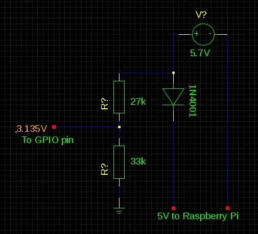
Before connecting these to your Raspberry Pi, measure the output voltages for the Raspberry and for the GPIO pins, the 1N4001 diodes normally have a voltage drop of around 0.7V but this diode being an general purpose diode they are not very precise. The voltage for the Pi should not exceed 5V and for the GPIO pin should not exceed the 3.3V.
By changing this schematic and using a voltage regulator LM317 (and giving it the correct resistor values on the ADJ pin , you can connect an 'off the shelf' power supply again), but this requires more components. This 'off the shelf' power supply can be 7.5V or 9V.
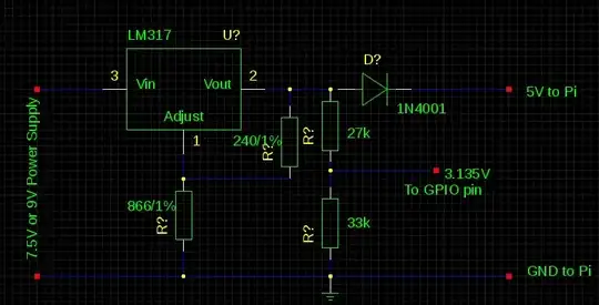
The LM317 needs 2 capacitors that are not in this schematic, please check the datasheet of the LM317 for these.