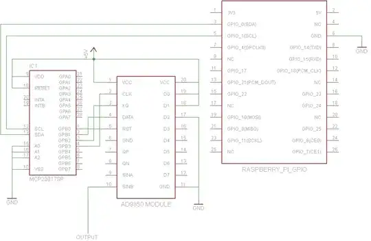
John La Rooy has a good solution but the circuit may be more complicated than some would prefer. This describes a similar solution designed by Tom Herbison using only the AD9850, although it uses 4 GPIO signal pins instead of 2 like John's solution.
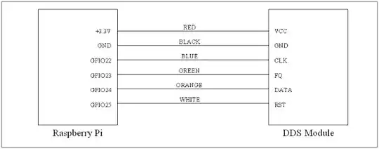
Tom connects to GPIO like this:
Notice he runs the AD9850 on 3.3V instead of 5V. According to this discussion, the AD9850 is rated to run at 3.3V or 5V, but some boards may use components not able to handle 5V for long, so running at 3.3V may actually be a better solution, depending on your flavor of AD9850 board.
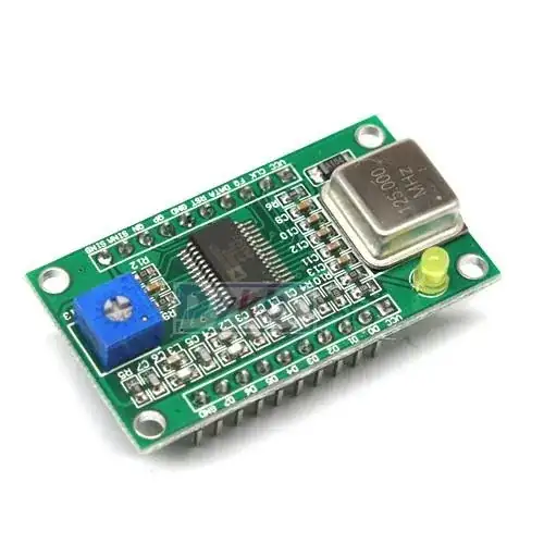
My particular AD9850 board had most of the pin labels only underneath the board, so I took a picture of the underside before pressing it down into a prototyping board. The pin locations ended up being identical to the ones on Tom's board anyway. On my board, FQ is labeled FU_UQ, CLK is W_CLK, and RST is RESET.
Tom provides this Python 3 script for controlling the function generator. Here's a copy of v1.0 in case the download link ever breaks:
# RPi RF Signal Generator v1.0

# Copyright (C) 2013 Tom Herbison MI0IOU
# Email (hidden to discourage spammers - see original rpi_rfsiggen.py file)
# Web <http://www.asliceofraspberrypi.co.uk>

# This program is free software: you can redistribute it and/or modify
# it under the terms of the GNU General Public License as published by
# the Free Software Foundation, either version 3 of the License, or
# (at your option) any later version.

# This program is distributed in the hope that it will be useful,
# but WITHOUT ANY WARRANTY; without even the implied warranty of
# MERCHANTABILITY or FITNESS FOR A PARTICULAR PURPOSE.  See the
# GNU General Public License for more details.

# You should have received a copy of the GNU General Public License
# along with this program.  If not, see <http://www.gnu.org/licenses/>.

# import GUI module
from tkinter import *

# import GPIO module
import RPi.GPIO as GPIO

# setup GPIO
GPIO.setmode(GPIO.BOARD)
GPIO.setwarnings(False)

# Define GPIO pins
W_CLK = 15
FQ_UD = 16
DATA = 18
RESET = 22

# setup IO bits
GPIO.setup(W_CLK, GPIO.OUT)
GPIO.setup(FQ_UD, GPIO.OUT)
GPIO.setup(DATA, GPIO.OUT)
GPIO.setup(RESET, GPIO.OUT)

# initialize everything to zero
GPIO.output(W_CLK, False)
GPIO.output(FQ_UD, False)
GPIO.output(DATA, False)
GPIO.output(RESET, False)

# Function to send a pulse to GPIO pin
def pulseHigh(pin):
    GPIO.output(pin, True)
    GPIO.output(pin, True)
    GPIO.output(pin, False)
    return

# Function to send a byte to AD9850 module
def tfr_byte(data):
    for i in range (0,8):
        GPIO.output(DATA, data & 0x01)
        pulseHigh(W_CLK)
        data=data>>1
    return

# Function to send frequency (assumes 125MHz xtal) to AD9850 module
def sendFrequency(frequency):
    freq=int(frequency*4294967296/125000000)
    for b in range (0,4):
        tfr_byte(freq & 0xFF)
        freq=freq>>8
    tfr_byte(0x00)
    pulseHigh(FQ_UD)
    return


# Class definition for RPiRFSigGen application
class RPiRFSigGen:
        # Build Graphical User Interface
        def __init__(self, master):
                frame = Frame(master, bd=10)
                frame.pack(fill=BOTH,expand=1)
                # set output frequency
                frequencylabel = Label(frame, text='Frequency (Hz)', pady=10)
                frequencylabel.grid(row=0, column=0)
                self.frequency = StringVar()
                frequencyentry = Entry(frame, textvariable=self.frequency, width=10)
                frequencyentry.grid(row=0, column=1)
                # Start button
                startbutton = Button(frame, text='Start', command=self.start)
                startbutton.grid(row=1, column=0)
                # Stop button
                stopbutton = Button(frame, text='Stop', command=self.stop)
                stopbutton.grid(row=1, column=1)


        # start the DDS module
        def start(self):
                frequency = int(self.frequency.get())
                pulseHigh(RESET)
                pulseHigh(W_CLK)
                pulseHigh(FQ_UD)
                sendFrequency(frequency)

        # stop the DDS module
        def stop(self):
                pulseHigh(RESET)

# Assign TK to root
root = Tk()

# Set main window title
root.wm_title('RPi RFSigGen')

# Create instance of class RPiRFSigGen
app = RPiRFSigGen(root)

# Start main loop and wait for input from GUI
root.mainloop()
Since any use of the GPIO pins on the pi requires running as root, Tom describes two methods of launching his python code with root privileges. His first method is to modify the Python IDE desktop icon to always run as root, but that strikes me as unsafe - you don't want to run all python GUI programs as root if you don't have to. The second method is to run sudo idle3_ from a command prompt to launch the Python 3 Integrated Development Environment with root privileges whenever it needs root privileges.
Tom doesn't mention installing the RPi.GPIO python 3 library so it may already be available on some Pi OS versions, but it was not available on the Occidentalis v0.2 I was using so I ran sudo apt-get install python3-rpi.gpio. Note that Python 3 uses a different location for RPi.GPIO so sudo apt-get install python-rpi.gpio will only make the library accessible to Python 2.
Once the Python 3 IDE is open with root privileges, open the file rpi_rfsiggen.py, then choose Run -> Run Module from the menu or press F5.
I was able to get a nice stable 18kHZ sine wave at 1Vpp from the SinB output pin (labeled ZOUT2 on my board) on my first try.