0

Just like a lot of people I'm using a RPi as a NTP server. There is a nice thread about it here: Switch out the X1 Oscillator on a RPI 2/3

User @colintd had a brilliant answer about switching the stock oscillator with a TCXO and he also mentions: "As a 3V3 part it needed AC coupling via a 1nF capacitor, and the DC level setting with 240K & 100K resitors"

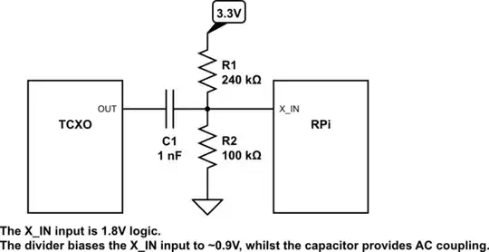
I was wondering if he (or anyone) can explain how this capacitor and resistors are connected? Perhaps a small circuit diagram?

Many thanks!

PS. As a newbie here I wasn't able to reply to the original thread, hence a new one.

1 Answers1

2

I tried to ping @colintd via a comment for you. I suppose they suggest making a DC voltage divider with R1=100K and R2=240K, and feeding it the AC signal from the TCXO via the 1nF capacitor.

schematic

simulate this circuit – Schematic created using CircuitLab

colintd
  • 357
  • 2
  • 10
Dmitry Grigoryev
  • 27,928
  • 6
  • 53
  • 144
  • Thanks for that. If I understand it right, the TCXO output signal is at 3.3V which is too high for the Pi. Using C1 and the voltage divider brings that signal level down to about 2.3V (according to my own quick calculations) which is an acceptable level for the Pi? – JohnnyBravo Oct 30 '20 at 14:41
  • @JohnnyBravo TCXO output is a mere 0.8V peak to peak, so the signal should be shifted to the right range for the Pi. Adding a DC 2.3V component makes it oscillate between 1.9V and 2.7V, which is apparently what the Pi's oscillator pin expects. – Dmitry Grigoryev Oct 30 '20 at 15:07
  • I went through the datasheet again for the TCXO that colintd had linked to and now I see the 0.8V peak peak and the voltage divider also makes sense now. Although I expect the pi to want a 3.3V square wave signal, it seems that 1.9V to 2.7V clipped sine is good enough.

    I might actually try an OCXO like this one https://www.iqdfrequencyproducts.com/products/details/iqov-162-2-02.pdf The output is a 3.3V HCMOS signal, so shouldn't need the capacitor and voltage divider if my thinking is correct.

    – JohnnyBravo Oct 30 '20 at 18:41
  • @JohnnyBravo Yes, you will likely not need that schematic with the oscillator you mention. – Dmitry Grigoryev Oct 31 '20 at 15:00
  • 1
    Really sorry for not replying earlier, but I have now updated the original answer with a full explanation, photos of the PCB connection point, and a schematic. https://raspberrypi.stackexchange.com/questions/117991/switch-out-the-x1-oscillator-on-a-rpi

    As the crystal oscillator in the Pi runs as 1.8V, we need the clipped sine signal rebiased to 0.9V. Having the 240K/100K divider, with 100K at the ground-end, gives the needed reference. (I have submitted an edit to the schematic above.)

    – colintd Jan 31 '23 at 14:46
  • 1
    @JohnnyBravo If you have a TCXO with 3V3 CMOS output, you will want to use a resistive divider on the output to reduce the range to 1V8. Two 100K resistors across the TCXO output, with the X_IN connected to the midpoint will work fine, giving a signal with a 1V65 range. Directly apply the 3V3 signal to a 1V8 input may be "exciting"! – colintd Jan 31 '23 at 14:58